
Stuck on an issue?
Lightrun Answers was designed to reduce the constant googling that comes with debugging 3rd party libraries. It collects links to all the places you might be looking at while hunting down a tough bug.
And, if you’re still stuck at the end, we’re happy to hop on a call to see how we can help out.
Have control state of qubits visible in the circuit drawing
See original GitHub issueFeature details
When using a controlled gate with custom control values, the drawing of the circuit does not represent this. The control values correctly show up in the mpl figure. Example:
dev = qml.device('default.qubit',wires=4, shots=100)
@qml.qnode(dev)
def circ():
    for i in range(4):
        qml.Hadamard(wires=i)
    qml.MultiControlledX([0,1,2],3,'010')
    qml.MultiControlledX([0, 1, 2], 3, '111')
    qml.MultiControlledX([0, 1, 2], 3, '000')
    return qml.probs(0)

print(qml.draw(circ)())
fig, ax = qml.draw_mpl(circ)()
fig.show()
0: ──H─╭C─╭C─╭C─┤  Probs
1: ──H─├C─├C─├C─┤
2: ──H─├C─├C─├C─┤
3: ──H─╰X─╰X─╰X─┤
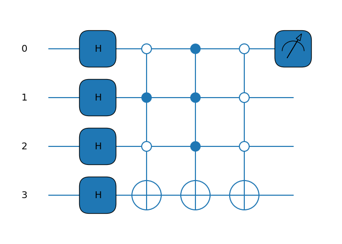
Implementation
Will have to fix different symbols for 0 and 1 control state. Maybe 0 state can be represented by an ‘O’ and keep ‘C’ for state 1.
How important would you say this feature is?
1: Not important. Would be nice to have.
Additional information
No response
Issue Analytics
- State:

- Created a year ago
- Comments:6 (6 by maintainers)
 Top Results From Across the Web
Visualizing a Quantum Circuit - Qiskit
When building a quantum circuit, it often helps to draw the circuit. This is supported natively by a QuantumCircuit object. You can either...
Read more >Quantum Circuit Diagrams - MITRE STEM
The result is that quantum circuit diagrams always show the qubits as straight horizontal lines, unlike classical circuits which can have ...
Read more >Visualizations - IBM Quantum
The live visualizations in IBM Quantum Composer show you different views of how quantum circuits affect the state of a collection of qubits....
Read more >Q-circuit Tutorial - UNM Physics & Astronomy
In this section, we'll learn how to draw. CNOT gates and controlled single qubit gates with an arbitrary number of controls. A simple...
Read more >Quantum Computing Lecture 1 Bits and Qubits What is ...
controlled transitions between them will do. 8. Qubits. Quantum mechanics tells us that any such system can exist in a superposition of states....
Read more > Top Related Medium Post
No results found
 Top Related StackOverflow Question
No results found
 Troubleshoot Live Code
Lightrun enables developers to add logs, metrics and snapshots to live code - no restarts or redeploys required.
Start Free Top Related Reddit Thread
No results found
 Top Related Hackernoon Post
No results found
 Top Related Tweet
No results found
 Top Related Dev.to Post
No results found
 Top Related Hashnode Post
No results found
Remember to add [unitaryhack] in the title for your PR @ankit27kh. And remember to sign up for the hack in case you haven’t already!
Hi @ankit27kh , The visual difference between
CandOis slight enough that I don’t think it makes a clear distinction.But I found the fixed-width unicode symbols
●and○. With those, aMultiControlledXwill look like:I actually really like how that looks, as it even more closely parallels the typical circuit drawing graphics. Thanks for the great idea 👍
Also, great catch on the
ControlledQubitUnitaryin the mpl drawer!It would be a great task for an external contributor as well.